
I will document here my adventures in the Class-E land. For those not
familiar with this excellent and easy technique for producing high power
extremely efficiently, there is no better introduction than the
Class-E RF Power Amplifiers paper,
by Nathan O. Sokal, WA1HQC.
This is what v1 of the amplifier looks like. I am using an IRF520.
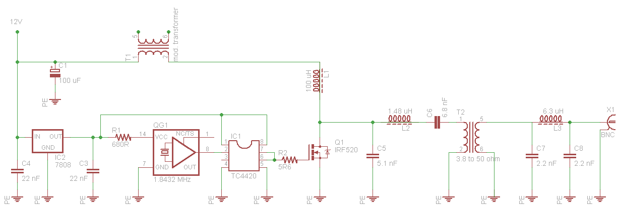
...and this is the schematic. The two caps in the
Class-E amplifier should be selected 20% components or combination of
fixed caps to give a capacitance as close as possible to the design value.

V = 13 V, I = 1.5 A, producing 16 W of RF.
I cranked up the voltage to 20 V and I got about 36 W from the poor IRF520.
It was still quite comfortable to touch and the only signs of distress came
from my cheap lab power supply...
This one is designed for 24 V and an IRF640 MOSFET (200V max drain-source voltage).
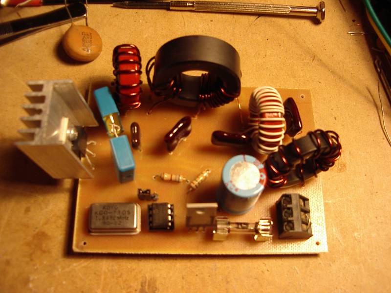
Things to notice are the use of silver-mica capacitors and the
much larger L1, which is now wound on a FT114-43 core.


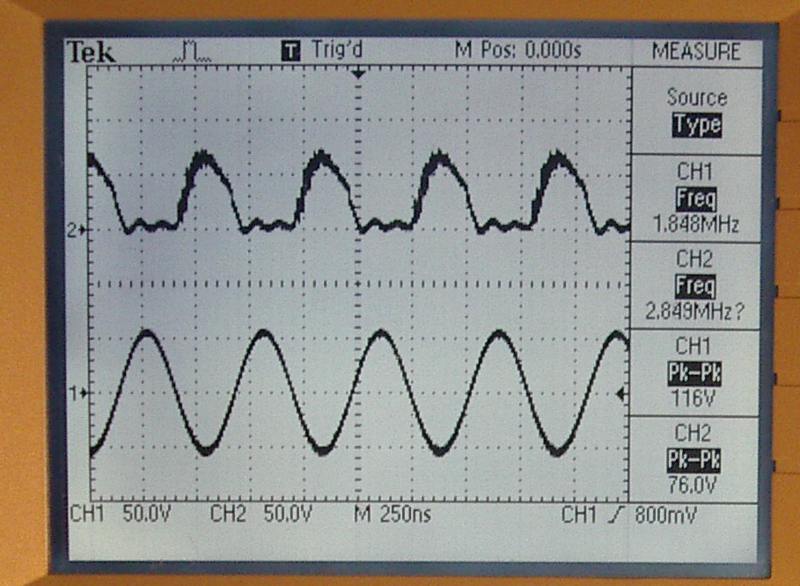
The oscillogram above shows the drain waveform (ch2) and the
output waveform (ch1) of the transmitter, operated at the design voltage
which is 24 V.
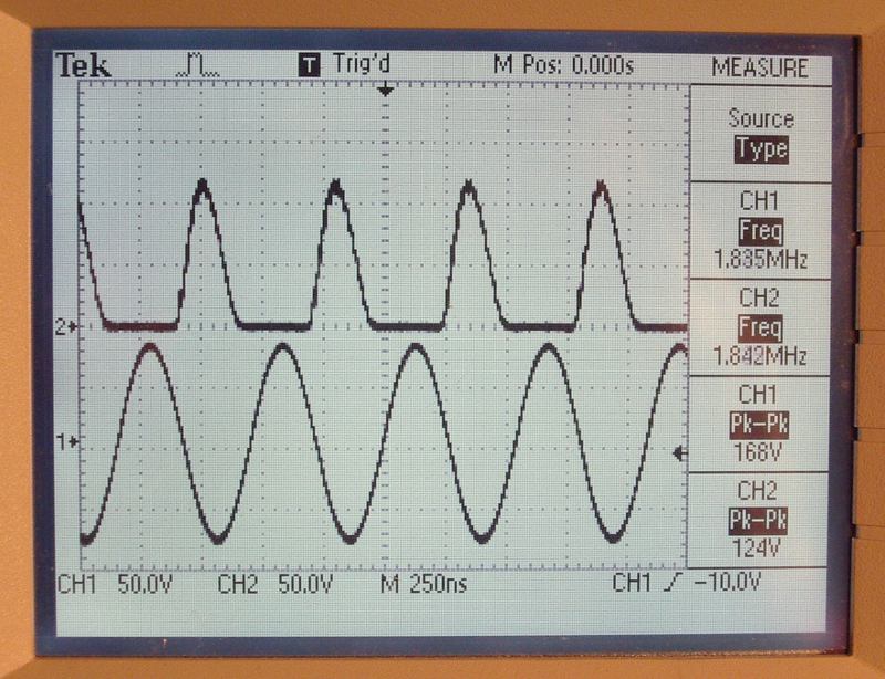
In this oscillogram, the voltage provided to the transmitter has been cranked up to 30 V (the max my PSU will give). As you can see, the power is now around 70 W and there is plenty of safety margin for the drain voltage.
For AM operation, I would suggest running this at a slightly lower than 24 V
to ensure that the drain voltage remains less than 200 V at the peaks of the
modulation. If you want to use this for CW (Morse code) only, then I think you
could increase the voltage to say ~34 V or so for an output power of 100 W, or
you can go even further up for more power, but keep an eye on the drain
voltage to ensure it doesn't go higher than 200 V. But, of course, 1.8432
MHz is not normally used for CW however it is permitted according to
the band plan.
A modulation transformer is trully a thing of the past. I believe
it will be very hard to find a transformer that will work well for
modulating this 160m transmitter, so the choices are two: either make
a transformer yourself or use a transformer that was designed for some
other task. Being lazy, I decided to try a number of different power
transformers that had the appropriate turns ratio. It turns out that
a big (300 VA) toroidal power transformer produced excellent results.
I used the two primary windings (110 V + 110 V) as the primary and
secondary circuits. The impedance presented to the audio amplifier
was close enough to the design impedance but of course, one could
easily add a few more turns on the toroid and make further adjustments.
With this setup, I had a very enjoyable QSO on 160 m AM with VK1DSH Dale
and VK1BEK John.