
A new band is about to be released to amateur radio operators around the world: 472 kHz to 479 kHz. In Australia, ACMA has ammended the LCD and access is allowed to advanced licence holders from 01/01/2013. It is not every day that a new chunk of the spectrum is opened up for experimentation, let alone a chunk in this historically interesting region. No commercial radio amateur gear currently supports 472 kHz for transmitting, so a transmitter has to be built from scratch.
I selected to build a transmitter using valves. In 2013, this is considered an odd decision. One could build a much more efficient (and less dangerous) transmitter using FETs in Class-D or E. However, I do like valves and I thought it is appropriate to build a valve transmitter for this traditional band.
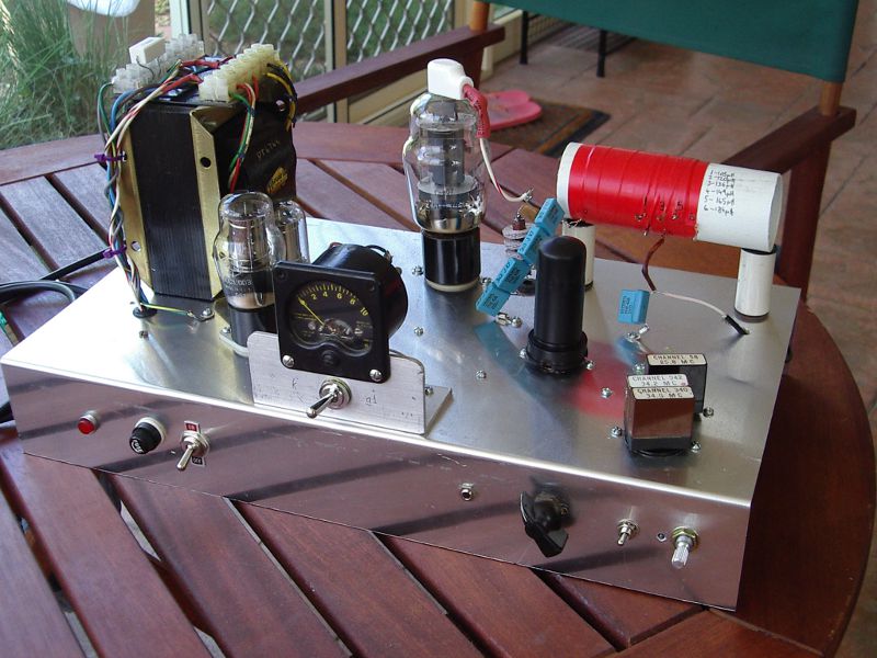
A soviet clone of the 6AG7 is used as the oscillator. The crystals are FT-241A type and were obtained from eBay. Note that FT-241A crystals are nowhere near as reliable as their cousins, the FT-243 ones. Out of six crystals, only three seem to be useable - the others are either producing very low output or do not oscillate at all. FT-241A crystals are marked with the final output frequency of the transmitter they were used with. They have fundamental frequencies in the LF/MF part of the spectrum and the ones to look for for using on 630 m are channels 55 to 58 and 340 to 343. A variable resistor at the cathode of the 6AG7 is used to ensure that the drive can be adjusted to compensate for the differences between crystals. The plate voltage for the 6AG7 is regulated by two OD3 valves and the screen voltage is produced from the plate voltage via a resistive divider. The oscillator circuit is the "electron-coupled" type from early ARRL handbooks.
The 807 is used in Class-C configuration. In fact, it is somewhere Class-B and Class-C, but that doesn't hurt anything but the efficiency of the transmitter. The pi-tank consists of fixed capacitors and inductor, calculated to match the 807 to a 50 ohm load. I used VK1OD's online calculators, I strongly recommend them to any valve entusiast. There are links to the calculator in the References section below.

A panel meter is used to display the 807 grid and cathode currents. The panel meter was salvaged from a 30 kW ISB tranmitter for HF, made by AWA. This transmitter was used by the department of plasma physics at the research school of physics and engineering, ANU, until it was replaced by more modern equipment.

The construction technique is typical of valve gear. It needs a bit of tidying up.

The inductor in the pi-tank is built on a piece of PVC pipe with a diameter of 44 mm. I added a few taps but ended up using the one at the calculated number of turns. The capacitors are polypropylene type; the plate tuning one consists of four 3n3, 2 kV capacitors in series and the load one consists of a 3n3 and a 1n5 capacitors in parallel. The capacitors were selected from my collection of 10% tolerance caps to produce the closest match to the calculated values. Beware of voltage derating as frequency increases!
The following schematic is an initial draft of the "as built" transmitter.

The transmitter produces an output power of 25 W on a 50 ohm dummy load. There is no noticeable chirp or other distortion. The following spectrograms are some of the reception reports from around the country. They were all received on 04/01/2013.
VK2DX (Sydney, NSW):

VK3DB (Moe, VIC):

VK3GJZ (Traralgon, VIC):

Edgar (Moonah, TAS):

VK4EBP (Brisbane, QLD):
