Indeed breaking news! The variometer was broken when I transmitted QRSS30 at about 60 W for an hour or so. The ferrite became really hot and eventually the inductance started dropping, so I had to adjust every few seconds! So there you are, this variometer is really convenient and will allow a limited antenna to get on air, but please don't use high power!
This page describes the variometer used for tuning the antenna to 136 kHz at the VK1SV LF station. Most antennas used by amateurs in the LF band are only a tiny fraction of the size they ought to be in order to resonate on 136 kHz without any assistance. It is therefore necessary to add some inductance in series with the antenna in order to bring its resonance frequency down to the 136 kHz band. It is also desirable to have the ability to vary that inductance by a bit, to allow tuning up an down the band - yes, you need to retune the antenna if you move say from 135.9 kHz to 137.7 kHz!
The common practice in the design and construction of such an inductor (known as the variometer) is to use an air core, single layer solenoid. To achive the variable inductance, a smaller air core solenoid is inserted in the outer solenoid and is mount in a way that allows the user to rotate it from 0 to 180 degrees. The relative allignment of the two solenoids defines the overall inductance of the variometer.
My variometer follows a different approach. Instead of using air core coils, I used a system that allows some ferrite to slide in and out of the coil in order to vary its inductance. This is certainly not a new idea, but it is not a very popular one because of the limitations in the power such a variometer can handle. A good description of the problems of using this approach can be found in DK5PT's web site.
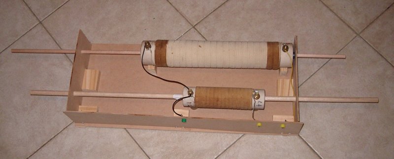
The configuration of the "ferrite kebab" variometer system can be seen in the picture below. There are two coils, in series, mounted on a wooden frame. The two yellow terminals are the two ends of the variometer. There are wooden sticks (dowels) that can slide in and out.

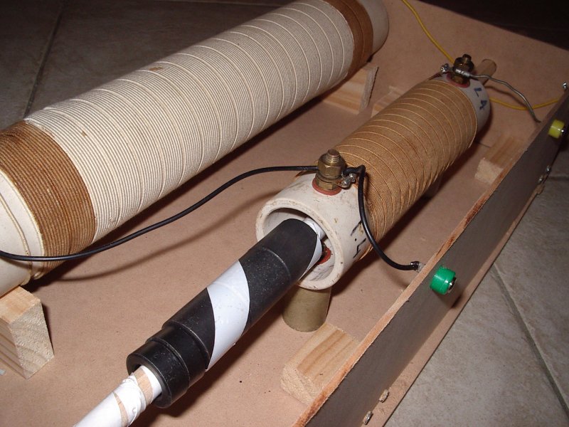
In the pictures below, the ferrite is out of the coil.

The ferrites are standard EMI type ferrites, harvested from old computer equipment (mostly power supplies).
It is interesting to note the construction of the coils. They are two layer solenoids, designed for high voltages. The winding is done in steps of about 1 cm. After winding about 1 cm of bottom layer, the wire will go back at the beginning of that 1 cm section and form another 1 cm winding on top of that. Then it will continue in the same direction to procude the bottom layer of the next 1 cm section. This technique ensures that the the potential is more evenly distributed along the coil, which makes it possible to work in such an application.

Both coils were salvaged from an old RF heating device which was decommissioned and destined to become landfill!
The total inductance of the two coils without any ferrite in their cores is 1.4 mH plus 2.8 mH = 4.2 mH. It is possible therefore to produce inductances ranging from a low value of 1.4 mH (bypass the big coil) to much more than 12 mH, by inserting multiple ferrite tubes on both cois. My antenna at this stage requires an inductance at the top of this range, but of course in the future I have plans of producing a more efficient antenna that will naturally require a much lower inductance to tune on 136 kHz.
Indeed this is a flexible system and it has proven so far to be a reliable option for a transmitter output power of up to 50 W. Limited tests at 100 W so far are encouraging that the system will be able to handle that power.